Retrofitting a Solar Site with BESS: Commission the New Control Boundary
Solar BESS retrofit commissioning should verify the site’s new control boundary before demonstrating energy savings. An existing PV system already has measurements, inverter settings and operating permissions. Adding a battery changes power flow and introduces another controller, but it does not automatically give that controller authority over the original equipment.
The EPC should begin with an as-built review and a shared sequence of operations. Meter location, current-transformer direction, source ownership and failure behaviour deserve attention early. This guide focuses on commissioning those interfaces, using a hypothetical power-balance example and documented cabinet configurations. It does not prescribe switching procedures for a live installation.
Key Takeaways
- Establish the actual existing configuration before selecting new control interfaces.
- Verify whole-site measurement and authority over every relevant source.
- Test low-energy, full-battery and lost-communications states as part of the retrofit.
On this page
- The existing system is an input, not a blank page
- Draw the new meter boundary first
- A hypothetical export condition reveals interface needs
- Give one controller authority over the site objective
- Test the states where the battery cannot help
- Environmental limits can alter the commissioned duty
- Keep a commissioning record that can be reproduced
- Buyer questions
The existing system is an input, not a blank page
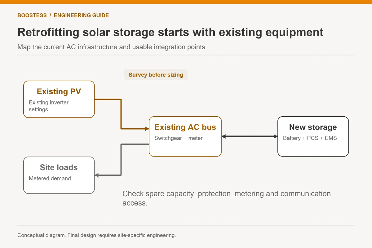
Obtain as-built drawings, inverter models, firmware versions, meter details, protection settings and connection conditions. Compare the documents with the installed equipment through authorised inspection. Mark discrepancies before using the drawing as the basis for a storage quotation.
Ask why the current PV operates as it does. It may have an export restriction, curtailment setting, power-factor requirement or another site-specific condition. Retain the source of each setting and identify who can approve a change. An installer should not overwrite an accepted configuration merely to make a new dashboard look consistent.
Review the PV manufacturer’s supported interfaces. A documented communication port does not establish that every third-party controller can change power safely or with the required timing. Obtain the protocol details, command permissions and approved compatibility information for the exact equipment revisions.
The DOE distributed energy interconnection checklist provides a reference for utility coordination. Apply it to the change in site operation, rather than assuming the original PV permission automatically covers storage charging, discharge or an added island mode.
Draw the new meter boundary first
Place the control measurement where it sees the power flow relevant to the project’s objective. Whole-site import or export control needs the relevant point-of-connection measurement. A battery feeder meter can verify battery energy but cannot by itself determine net site exchange when independent PV and loads remain elsewhere.
Show every source and significant feeder on the updated one-line drawing. Identify any equipment outside the chosen measurement boundary and explain why. A source accidentally excluded from the controller’s view can make the calculated power balance appear correct while the utility sees a different result.
Verify current-transformer phase mapping and direction using approved methods. The commissioning record should state how the sign changes during battery charging, discharging and site export. Consistent labels on a screen are not sufficient evidence unless their relationship to actual power flow is checked.
Align the old and new measurement systems in time. If an existing PV portal updates slowly while the local connection meter updates rapidly, their instantaneous readings may not reconcile. Distinguish a normal timing difference from a wiring or scaling error. Use an agreed reference and sampling method for acceptance.
The AC-coupled versus DC-coupled discussion explains broad topology options. In a retrofit, the decisive drawing should show the installed boundary, control path and permission for each source rather than stop at the topology label.
A hypothetical export condition reveals interface needs
Assume an existing PV site produces 400 kW while consuming 250 kW. Its conceptual export is 150 kW. If the project’s permitted export in this illustration is 50 kW, storage must absorb 100 kW or the PV controller must curtail that amount while the condition persists.
Now let site load fall to 150 kW. Required absorption or curtailment becomes 200 kW under the same PV output and export allowance. The retrofit needs a coordinated response to that load change. A battery selected for the first condition cannot be assumed to absorb the second simply because its nominal energy looks large.
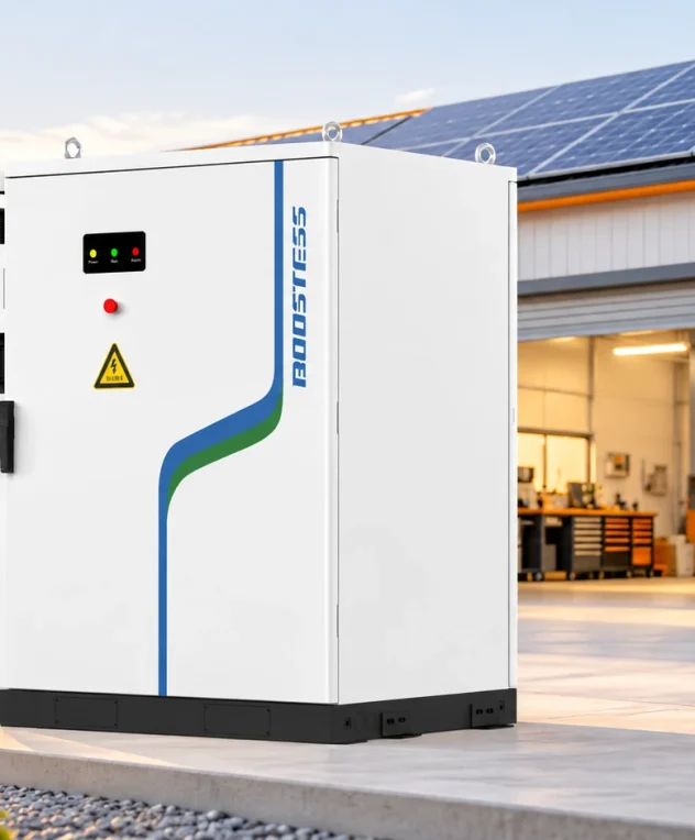
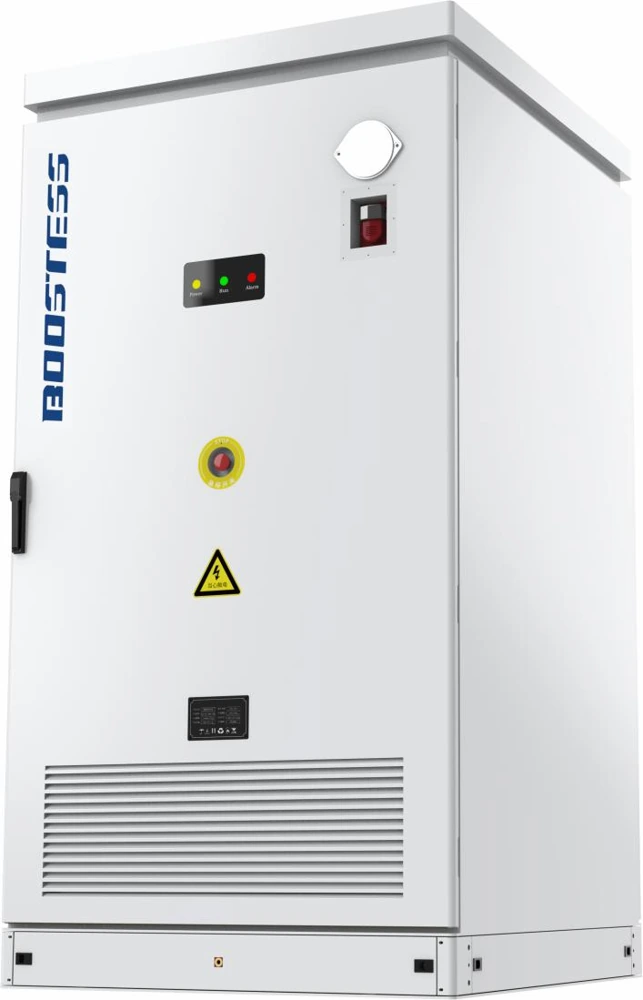
The BOOSTESS brochure describes a 105 kW / 241 kWh air-cooled AC cabinet with integrated conversion equipment and a 241.152 kWh nominal battery. Its rated AC output does not prove a guaranteed 100 kW charge acceptance in the example. Obtain charging-power evidence and the offered controller’s interface with the existing PV equipment.
The 125 kW / 261 kWh liquid-cooled cabinet is another documented configuration to compare. Its greater nominal output and energy do not establish coordinated control of the original PV inverters. In both cases, the quotation must identify available charge power, operating conditions, usable headroom and supported curtailment interfaces.
For the 100 kW absorption case lasting thirty minutes, 50 kWh crosses the assumed charging boundary. Use that calculation to define the test duty, then account for actual headroom and losses. Keep the example separate from a guaranteed product duration or measured site result.
Give one controller authority over the site objective
Define who owns the whole-site power limit. The original PV export controller, new battery EMS and remote platform may each attempt to regulate the same measurement. Without coordinated authority, one device can charge while another curtails unnecessarily, or several devices can repeatedly react to each other’s changes.
Create a command hierarchy showing the connection constraint, protective limits, battery restrictions, PV permissions and operator requests. Identify which device enforces each limit locally and how another device learns that it is active. The hierarchy should match both the installed wiring and software configuration.
Document the supported data and command paths. A read-only integration can improve visibility but cannot necessarily control PV output. A writable interface needs command validity, acknowledgement and timeout rules. Avoid describing both as “communication enabled” when their functions differ materially.
The DOE battery-storage technical specifications template includes communication and operating-sequence requirements. Use that procurement concept to request a retrofit-specific narrative. The template does not establish compatibility between the particular old and new equipment on this site.
Test the states where the battery cannot help
A partly empty battery on a sunny day is the easiest retrofit demonstration. Include full charge, limited charge power, a protective stop and maintenance unavailability in the control review. The site needs an approved response to surplus generation even when storage cannot absorb it.
Examine low-energy discharge as well. If the battery reaches its routine reserve floor, a demand-management request may no longer be achievable. The controller should report the restriction and follow the agreed operating priority. The owner’s model should not assume the same dispatch capacity throughout every day.
Separate loss of the internet from loss of the local connection meter or PV control path. A cloud portal may stop showing data while local control continues; losing a required local measurement can have a different consequence. Specify the response to each event, including operator alarms and the accepted fallback arrangement.
Recovery is part of the test. After communications return, the controller should reconcile current measurements, active limits and equipment state before resuming normal commands. Do not allow a historical request to become a fresh instruction without the agreed validity checks. Record the transition so that the owner can verify it.
Environmental limits can alter the commissioned duty
The documented 105 kW / 241 kWh cabinet’s operating range includes derating above 45°C. A retrofit study should therefore use the site’s expected conditions and the offered equipment’s actual derating evidence, rather than testing only during a mild commissioning day. The same nominal rating may not remain available through the project’s demanding period.
Installation position can affect those conditions. Confirm approved clearances, airflow, exposure and service access from the offered variant’s documents. Existing solar-site space is not automatically suitable for storage. Cable routes and meter placement should also remain compatible with the revised control boundary.
Record auxiliary demand and its measurement boundary. Cooling and standby energy can affect site imports and the battery’s daily balance. The retrofit evaluation should distinguish battery charge/discharge energy from whole-site change, especially when comparing the new system with the original PV baseline.
Keep DC battery and AC conversion measurements labelled in the test dataset. The 241.152 kWh nominal battery figure in the air-cooled cabinet brochure belongs to the battery boundary, while its 105 kW rated output describes the AC equipment. A retrofit report should show actual energy at the agreed AC boundary and site exchange at the connection. Distinct labels prevent a comparison of unlike values from appearing to prove usable capacity or whole-site efficiency.
Keep a commissioning record that can be reproduced
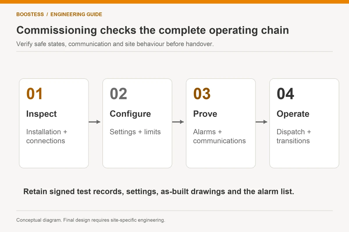
Before testing, capture drawings, equipment models, firmware, meter scaling, controller settings and connection limits. Define which configuration each test proves. If a supplier changes software during commissioning, repeat the affected scenarios or document an approved evidence basis for accepting the change.
Use test cases linked to the site’s actual objectives: import reduction, permitted export, charge scheduling or approved backup. Record the relevant power boundary, time resolution, commands, SOC and alarms. The acceptance report should identify pass criteria and limitations rather than present a set of favourable dashboard screenshots.
Retain the final configuration with the operator’s handover documents. Include a process for reviewing future PV expansion, replacement inverters and new loads. A control scheme commissioned against one arrangement cannot be assumed valid indefinitely after the site changes.
Buyer questions
Can storage be added without changing the existing PV inverter?
Possibly, depending on the chosen topology, supported interfaces and operating objective. Verify the actual equipment and permissions. Even where the inverter remains, metering and control coordination may need changes.
Does successful battery discharge prove retrofit acceptance?
It proves only the defined discharge test. Acceptance also needs the relevant site-limit, charging, failure and recovery evidence. Test the control boundary that the owner will rely on in everyday operation.
What is the most useful pre-purchase deliverable?
Request an updated one-line drawing and an operating-state table with evidence owners. Those documents expose compatibility and authority gaps while the design can still change. They also provide the structure for a commissioning programme tied to the site’s actual requirements.