Solar-Diesel-Battery Microgrids: Keep Generator Limits in the Dispatch Plan
A solar diesel battery microgrid needs generator operating limits inside its dispatch plan. The battery can absorb power only while charge headroom and charging capability remain available. When those conditions change, the controller must coordinate generator output, PV curtailment and loads through an approved sequence.
There is no universal minimum generator loading percentage suitable for every installation. Obtain the actual generator manufacturer’s limits and service guidance, then assess the offered hybrid equipment and site architecture. This guide uses a small hypothetical system to explain the power balance, the questions behind a dispatch schedule and the evidence required before commissioning.
Key Takeaways
- Obtain generator-specific loading, ramping and parallel-operation requirements.
- Model a full battery as an expected dispatch state.
- Verify source transitions and recovery as well as steady energy balance.
On this page
- Identify the generator’s permitted operating envelope
- A hypothetical small-system power balance
- Use the hybrid cabinet’s documented interfaces
- Charge headroom must be planned before the sunny period
- Treat starts and stops as a sequence, not a threshold
- Ask for an operating narrative the owner can audit
- Verify the difficult states before acceptance
Identify the generator’s permitted operating envelope
Request the generator’s model, rated output, controller details and manufacturer documentation for the intended duty. Establish permitted loading, starting and stopping conditions, ramp behaviour and any restrictions on prolonged operation. Mark unknowns in the project brief rather than filling them with generic percentages.
The source interface also matters. Confirm the generator’s voltage, frequency, neutral and earthing arrangement through the responsible electrical design. Ask which control and status signals are available and which equipment can request a start or stop. A drawing that connects the generator to a port does not establish all these functions.
Keep generator protective functions and microgrid dispatch authority separate. Local protections must retain their approved role. The supervisory controller should act within the authorised operating envelope and report when a requested state is unavailable. Operators need to see the reason, rather than an unexplained refusal to dispatch.
The DOE microgrid development checklist provides a planning reference for coordinating sources and loads. For this project, attach the actual generator limits and source-control responsibilities. The checklist does not verify a particular generator and hybrid inverter combination.
A hypothetical small-system power balance
Assume a conceptual site uses a 40 kW generator. For illustration only, suppose the project’s verified operating requirement were a 12 kW minimum while that unit remains online. This is an invented example input, not a recommended generator setting. Actual minimum loading must come from the relevant equipment and duty assessment.
During a sunny low-load period, assume site demand is 18 kW and PV output is 20 kW. With the generator at the example’s 12 kW minimum, total available generation is 32 kW. The site therefore needs to absorb or curtail 14 kW to balance the assumed demand.
If the battery can accept 14 kW in that state, charging can provide the sink. Over one hour, 14 kWh crosses the charging boundary before the actual stored-energy and auxiliary effects are considered. If the battery cannot charge, the system needs an approved alternative. Holding the generator at 12 kW would leave room for only 6 kW of PV under the example’s constant-load assumptions.
Now suppose a cloud reduces PV output to zero while demand remains 18 kW. At the existing 12 kW generator output, a temporary 6 kW gap appears. Battery support, generator response or another permitted action must address it. The model should represent the transition, not only the balanced sunny and cloudy endpoints.
| Hypothetical state | Load | Generator | PV | Balancing requirement |
|---|---|---|---|---|
| Sunny, charge available | 18 kW | 12 kW | 20 kW | Absorb 14 kW |
| Sunny, battery full | 18 kW | 12 kW | Limit to 6 kW | Curtail remaining PV |
| Cloud arrives before generator response | 18 kW | 12 kW | 0 kW | Supply temporary 6 kW gap |
These arithmetic cases do not establish stability, protection coordination or operating approval. They identify the duties that the engineering assessment must address.
Use the hybrid cabinet’s documented interfaces
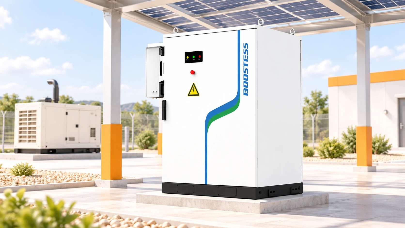
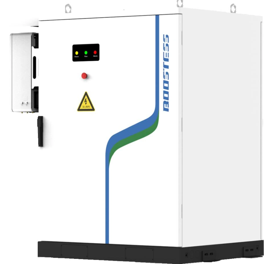
The BOOSTESS brochure describes a 50 kW / 100 kWh hybrid cabinet with LFP storage and a source diagram including PV, grid and a diesel generator. Its inverter table lists a 50 kW maximum generator input. That is a documented interface rating, not proof that every generator below 50 kW is compatible.
The hypothetical 40 kW generator is below that listed input power, but voltage, control, protection and operating-mode compatibility still need confirmation. Obtain the exact offered inverter configuration and approved generator integration information. Do not substitute another variant’s communication or switching claims.
Similarly, the 100 kWh nominal battery describes equipment energy, not unlimited absorption capability. Available charge power can depend on state, temperature and configured limits. Ask the supplier to show how the system handles the example’s 14 kW charging duty and what happens when the energy headroom ends.
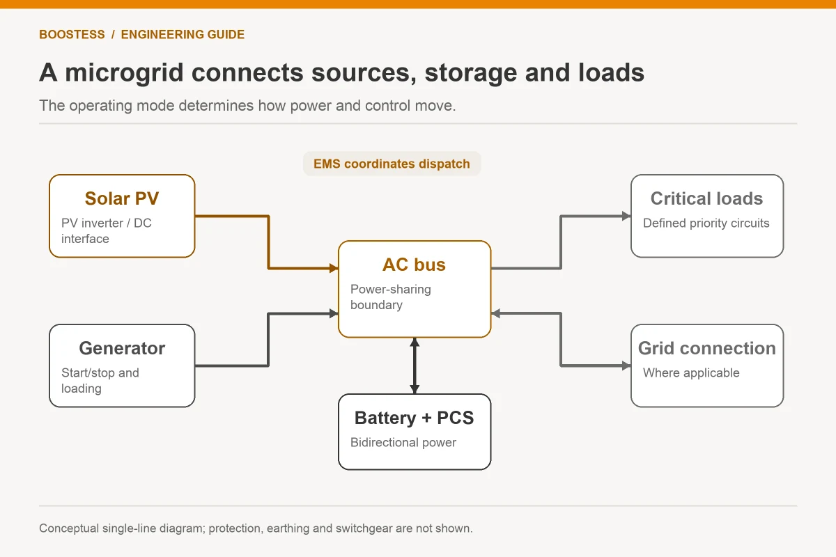
The solar and storage topology explanation provides broader architectural context. In this small microgrid, the decisive deliverable is a source-specific sequence with clearly assigned authority. A topology label alone cannot resolve generator dispatch.
The same hybrid-cabinet brochure distinguishes a recommended 100 kW PV array from 96 kW maximum usable PV input. Preserve that distinction when selecting the solar side of the small-system example. Array nameplate, usable inverter input and actual daytime production are different quantities. Ask the supplier to confirm the approved input configuration rather than treating the largest printed PV number as power available at every hour.
Charge headroom must be planned before the sunny period
If the operating plan keeps the generator online during daytime PV production, calculate how much battery headroom the resulting surplus needs. Integrate the power difference across the actual load and solar profile. Do not multiply the maximum surplus by every daylight hour unless that conservative assumption is intentional and disclosed.
Reserve for an outage or night duty can conflict with daytime charging headroom. A battery already held at a high reserve may have little room to absorb the combined generator and PV output. The owner should approve the priority between reserve, renewable use and generator operating requirements.
Stopping the generator may be an option in an approved architecture, but it requires verified source roles and sufficient battery power and energy. Identify which equipment establishes voltage and frequency after the generator stops, and whether the loads remain compatible. Do not assume a hybrid product’s energy capacity proves that mode.
The DOE explanation of distributed resources and microgrids provides context for islanded operation. It does not establish model-specific grid-forming or black-start capability. Request evidence for the proposed state and validate the complete site design.
Treat starts and stops as a sequence, not a threshold
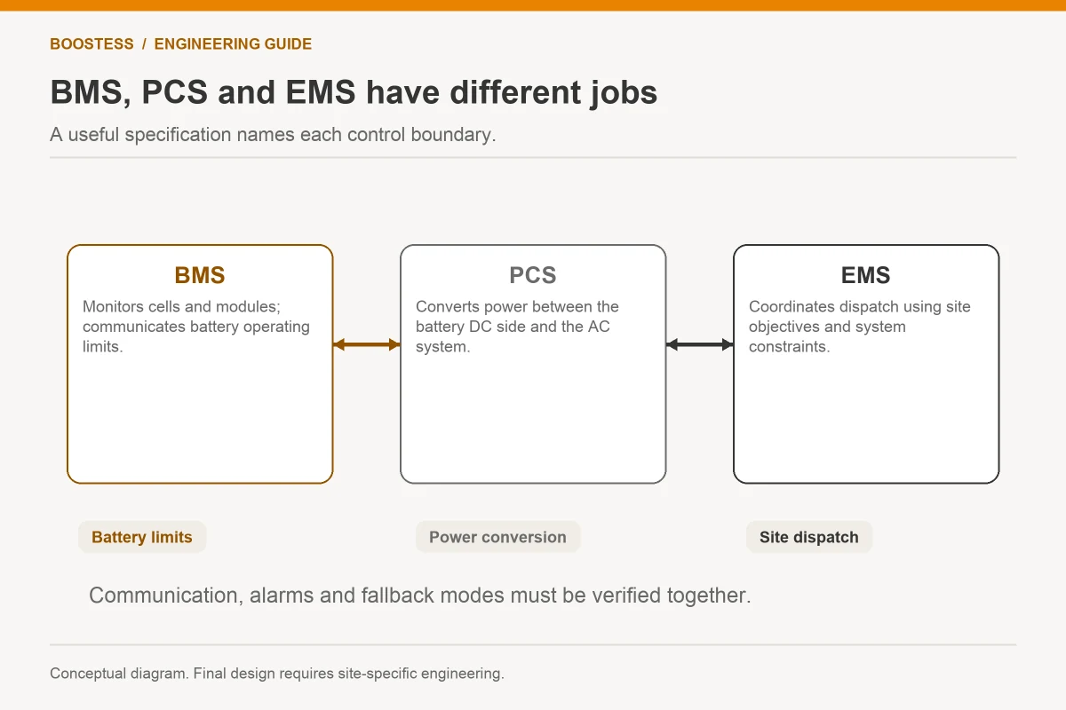
A simple rule such as “start the generator when SOC reaches a chosen value” is only part of the operating logic. The sequence needs to account for start readiness, unsuccessful starts, warm-up where required, connection permission, output ramping and battery reserve during the transition. Obtain the equipment-specific requirements.
Define what happens if the generator is unavailable. The controller should report the condition and follow the approved reserve and load-priority plan. An unattended system cannot rely on an operator discovering a failed start from declining SOC alone. State the local alarm and escalation responsibilities.
Stopping needs coordination too. Verify which source carries the load during the transition and how the system handles a subsequent load increase. Use appropriate delays and operating constraints from the approved design, rather than publishing a universal cycling rule. Frequent starts may change maintenance requirements, so include the generator service implications in the commercial assessment.
Review the BESS versus diesel generator comparison for wider equipment roles. A combined system should demonstrate how the sources work together under the selected rules. Their strengths do not automatically add up when their controllers conflict.
Ask for an operating narrative the owner can audit
Require a state table covering normal generation, limited battery charging, full battery, low reserve, generator unavailable, lost measurement and communications recovery. For each state, name the active power limits, source authority, load priorities and operator indication. This table should match the installed controller configuration.
Show where reverse-power prevention and other required protective functions reside in the approved design. Do not treat battery charging as the sole means of handling surplus; charging can become unavailable. The responsible designer should identify the required protection and control measures for the actual generator interface.
The owner’s operating team should be able to explain the expected response to a full battery and sudden load reduction. If the answer is unclear, the supplier has not yet supplied a complete dispatch narrative. Resolve that gap while the system is still on paper.
Verify the difficult states before acceptance
Use approved tests or simulations to verify the agreed source transitions, loss of charge availability, load steps and unsuccessful generator-start response. Record which conditions were witnessed on site and which were validated by another method. Do not present a simulation as a completed field result.
Retain time-stamped source power, battery state, commands, alarms and bus measurements. Define the acceptance conditions and permissible disturbances with the responsible designers. A balanced energy spreadsheet and a successful normal-mode run provide different evidence; the project needs both where relevant.
Check recovery after an exception. When the generator returns or communications reconnect, the controller should reconcile current conditions before resuming dispatch. An old command should not cause an unexpected state change. Preserve the tested software revisions and settings at handover.
Does battery storage guarantee lower diesel consumption?
No. The outcome depends on load, generator operation, renewable production, recharge losses and controls. Evaluate it with the actual fuel data and agreed operating model, then distinguish projected effects from measurements.
Can the minimum generator loading be copied from another project?
It should not be assumed. Obtain the actual generator manufacturer’s requirements and the approved duty assessment. That prevents a convenient modelling input from becoming an unsupported operating instruction.
What should the quotation prove?
It should identify compatible equipment, available charge and discharge functions, supported modes, operating limits and acceptance evidence. Keep exclusions visible. This gives the owner a complete multi-source operating proposition rather than three connected equipment labels.