
BESS Interconnection: Prepare the Utility Data Package Early
BESS interconnection documents should be prepared while the site and operating concept are still being defined. A manufacturer datasheet describes equipment, while a utility reviews how that equipment affects a particular connection. Confusing the two can leave an EPC with a complete storage order and an incomplete connection application.
Early preparation gives the owner a chance to resolve the delivery point, export behaviour, protection interfaces and responsibility for studies before equipment choices become difficult to change. This guide describes a practical data package and revision process. It is a planning framework; the applicable utility and jurisdiction determine the final submission and approval requirements.
Key Takeaways
- Define every intended operating mode before submitting inverter and protection information.
- Keep manufacturer evidence separate from site studies and utility acceptance.
- Manage drawings, settings and software revisions as one consistent connection package.
On this page
- Connection planning is part of equipment selection
- Make the one-line drawing the document index
- A product example shows why boundaries matter
- Describe operating modes as observable behaviour
- Protection evidence needs the exact configuration
- Set a single owner for the revision register
- Turn the application into an acceptance plan
- Buyer questions
Connection planning is part of equipment selection
In its September 2026 grid modernisation report, the IEA identified at least 600 GW of advanced-stage utility batteries awaiting connection in 2025. The IEA executive summary supports the need for early connection planning. It does not predict the schedule of an individual commercial or industrial project.
For a site project, begin by identifying the connection applicant, utility contact, delivery point and available connection capacity. Determine which studies the utility expects, who performs them and whether equipment changes trigger a revised application. Build these requirements into the procurement schedule.
Ask what the connection permits the battery to do. Importing energy, exporting energy, supporting islanded loads and operating alongside PV or a generator can require different information. A proposal that says “grid connected” without naming the intended modes is too broad for an accurate review.
Keep the grid-connected storage design discussion as background. The application should replace its general diagrams with the site’s actual topology, ratings and agreed source responsibilities. A project-specific drawing is the starting point for meaningful utility questions.
Make the one-line drawing the document index
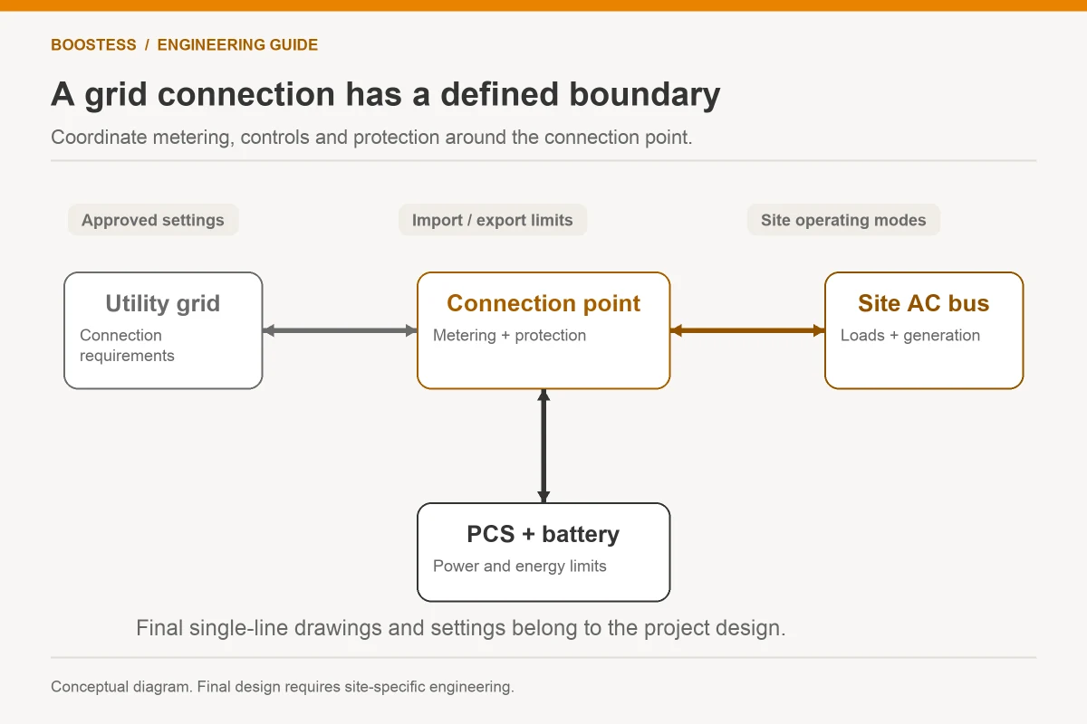
The one-line drawing should show the point of connection, transformer where applicable, switchgear, protection devices, storage conversion equipment, PV and generators, metering and supported-load boundaries. Use consistent equipment identifiers so every supporting document can refer to the same components.
Attach ratings and ownership at the appropriate boundaries. Nominal battery DC voltage does not establish the connection voltage, and PCS output does not necessarily equal power at the utility delivery point. Identify the equipment between those points, including auxiliaries and any project losses that belong in the performance boundary.
Show metering used for control separately from revenue metering. Explain which measurement enforces export or import constraints and what happens if it becomes unavailable. If several controllers share a site, identify the master authority and communication paths. An unlabeled EMS box does not explain who can issue the relevant commands.
The DOE distributed energy interconnection checklist offers a process reference for utility questions and stages. Use it to organise discussions, then record the actual answers beside the drawing. Do not present the checklist as a universal list of approval documents.
A product example shows why boundaries matter
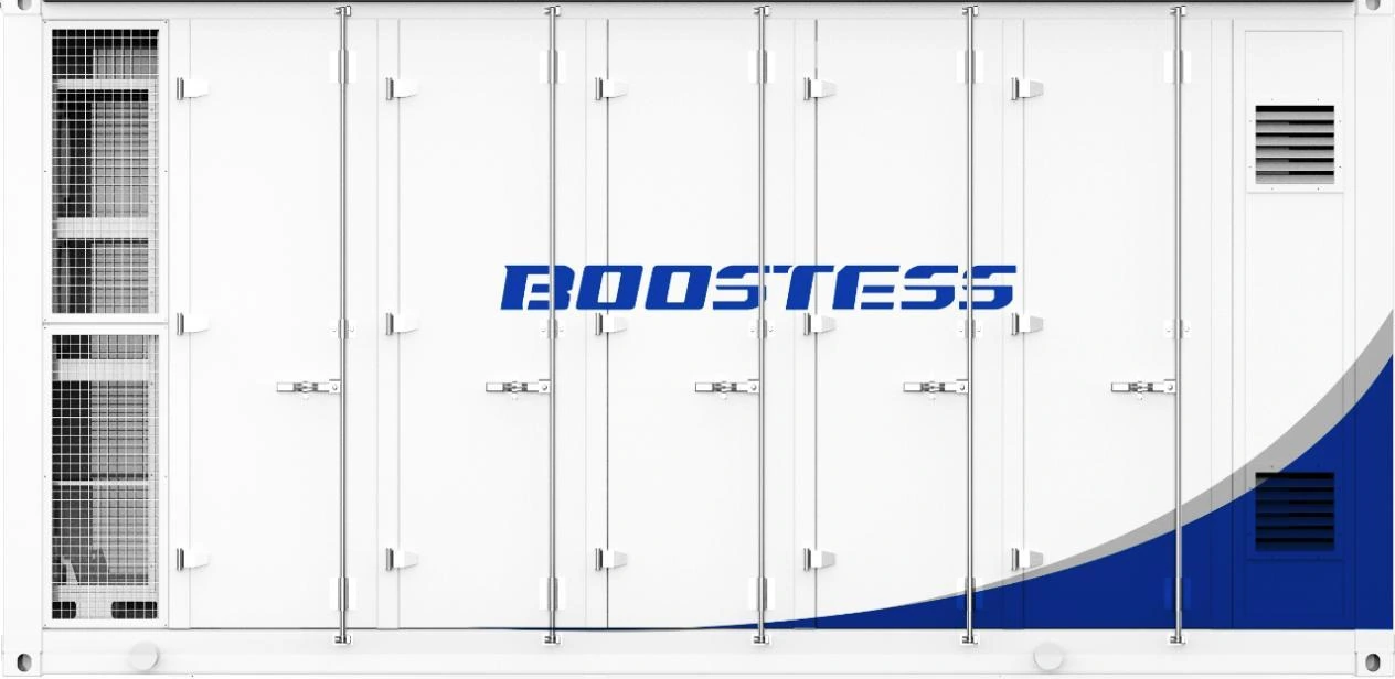
The BOOSTESS brochure’s 5 MWh liquid-cooled container specifies 5,015 kWh nominal battery energy. Its associated AC equipment table lists 2,500 kW rated output and 690 Vac. These are documented equipment values, not a declaration that the utility connection accepts 2.5 MW at 690 V.
If a hypothetical project intends to connect at a different voltage, the package must identify the appropriate transformer and electrical interfaces through the approved design. Obtain their actual ratings, impedance information, protection data and operating responsibilities. Do not infer that a transformer is included from the container’s storage-energy label.
The nominal energy-to-power ratio is about two hours, calculated as 5,015 kWh divided by 2,500 kW. That ratio describes equipment scale. It does not establish usable export duration, connection permission or the energy available after reserve and auxiliary consumption. Keep those questions in separate rows of the application and procurement record.
A smaller integrated cabinet presents the same boundary issue at a different scale. Its rated low-voltage output still needs a site network assessment and utility review where applicable. The EPC should use the exact offered variant’s documentation, rather than another product in the same energy-capacity family.
Describe operating modes as observable behaviour
Prepare a mode table that a reviewer can understand without interpreting marketing terminology. For each mode, identify whether the site imports or exports, which source establishes voltage and frequency, which loads are supported and what limits govern power. Mark modes that are proposed but not yet approved.
Include charging behaviour. A battery can create a material import demand while charging, even if the initial sales discussion concentrates on discharge. State the proposed maximum import, scheduling constraints and interaction with existing site load. The connection assessment needs both directions of power flow.
Where islanded operation is proposed, distinguish intentional islanding from protective disconnection and unintentional islanding protection. Obtain the complete switching and control narrative from the responsible designers. Battery energy and an “off-grid” brochure application do not establish the site’s approved island arrangement.
Use a compact submission table:
| Proposed state | Information to disclose | Evidence owner |
|---|---|---|
| Routine charging | Maximum import and site-load coordination | EPC and controls supplier |
| Routine discharge | Export limit and delivery-point power | EPC and equipment supplier |
| Restricted or zero export | Meter boundary, control response and fallback | Site controller supplier and EPC |
| Approved island operation | Source roles, switching and supported loads | Responsible electrical designers |
| Recovery to grid operation | Permission sequence and control coordination | EPC, utility and relevant suppliers |
The table assigns questions, not universal operating rules. The project team should amend it to match its actual topology and utility requests.
Use a boundary register for the container proposal: battery nominal DC energy and voltage, PCS rated AC output, project transformation equipment, auxiliaries and utility delivery point. Assign a document owner to each row. The supplied brochure gives the battery and associated PCS figures, while the EPC must obtain the remaining site design evidence. That register prevents a bid from presenting a container rating as if it already described the complete utility interface, and helps the reviewer trace which values are final and which remain assumptions.
Protection evidence needs the exact configuration
Ask the utility and responsible protection engineer which device data, studies and settings are required. Keep inverter protection functions distinct from site protective devices. Evidence for a component’s standards compliance does not automatically prove coordination across the installed network.
The BESS switchgear discussion provides context for this equipment boundary. The connection package should include the actual switchgear and protection arrangement, with document revisions and responsible approval. Avoid substituting a generic catalogue page for model-specific information.
Record which inputs remain provisional. A transformer selection, cable length or protection device change can affect a study. The reviewer needs to know whether the submitted result reflects final equipment or an assumed design. Assign deadlines for closing those inputs before commissioning.
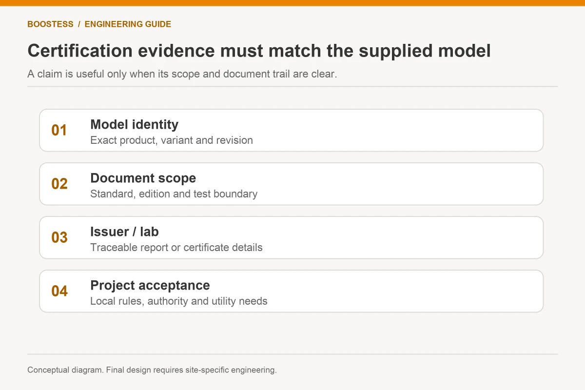
Do not treat a manufacturer certificate as utility acceptance. Standards evidence can support the equipment portion of the review, but the utility may also need site studies, settings, tests and operating agreements. Track each approval item separately so that a checked certificate does not hide an unfinished application.
Set a single owner for the revision register
A connection package often crosses several suppliers. The EPC should appoint someone to maintain a master register linking drawings, equipment models, study inputs, firmware versions, settings and submission dates. Each changed item needs an impact assessment on the rest of the package.
Use the same identifiers in purchase orders and drawings. If the equipment supplier changes the offered inverter, do not let a commercially equivalent substitution bypass the electrical review. Obtain updated documents and confirm whether the utility or designer needs to reassess the configuration.
Keep a record of questions and decisions. A utility email clarifying a mode or limit may be as relevant to the final operating arrangement as a drawing revision. Summarise the decision with its source and owner, then link it to the applicable document. This avoids relying on one person’s memory at handover.
Plan a freeze point for commissioning. The installation and test team should receive a consistent approved set, with a defined process for exceptions discovered on site. Using several almost-final revisions creates ambiguity about which configuration the acceptance test is meant to prove.
Turn the application into an acceptance plan
Map every material operating commitment to evidence at commissioning. The test method should identify the measurement boundary, relevant operating state, permitted tolerance and witnessing responsibility. Use utility-approved procedures where required and the site’s authorised safety arrangements.
Record the installed configuration before testing. Verify meter direction, protection settings, controller limits and equipment revisions against the submitted package. A successful test on different settings cannot confirm the original application unless the change is documented and accepted.
Retain the final drawings, approval conditions and test records with the operator’s sequence of operations. The operator should know the approved envelope and the changes that require a new review. Capacity expansion, new PV, a changed transformer or a different dispatch service can all affect the connection package.
Buyer questions
Can interconnection start before the final supplier is chosen?
Often the project can begin discussions and establish required information early. Mark preliminary inputs clearly and confirm the utility’s process. Final equipment selection must remain consistent with the accepted studies and documents.
Which documents should the manufacturer provide?
Request the offered model’s electrical ratings, control interfaces, protection functions, applicable standards evidence and any required study information it can supply. The EPC must still assemble the site package and obtain the necessary reviews.
Does successful factory testing establish connection approval?
No. Factory evidence verifies defined equipment tests. Connection approval and site acceptance concern the installed network and agreed operation. Preserve the distinction in the schedule, responsibility matrix and handover records.