BESS Site Selection: Review Flood Exposure, Access and Maintenance Space
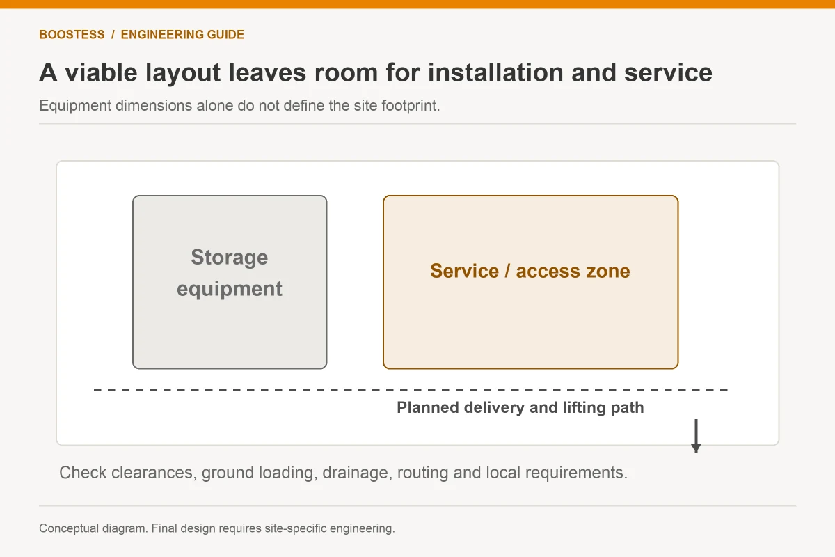
A good BESS location must work during delivery, daily operation, maintenance and an emergency. Review flood exposure, drainage, vehicle access, cooling airflow and service space before fixing the equipment footprint. A cabinet that fits on a drawing can still occupy the route needed to replace a module or prevent the site from reaching its emergency isolation point.
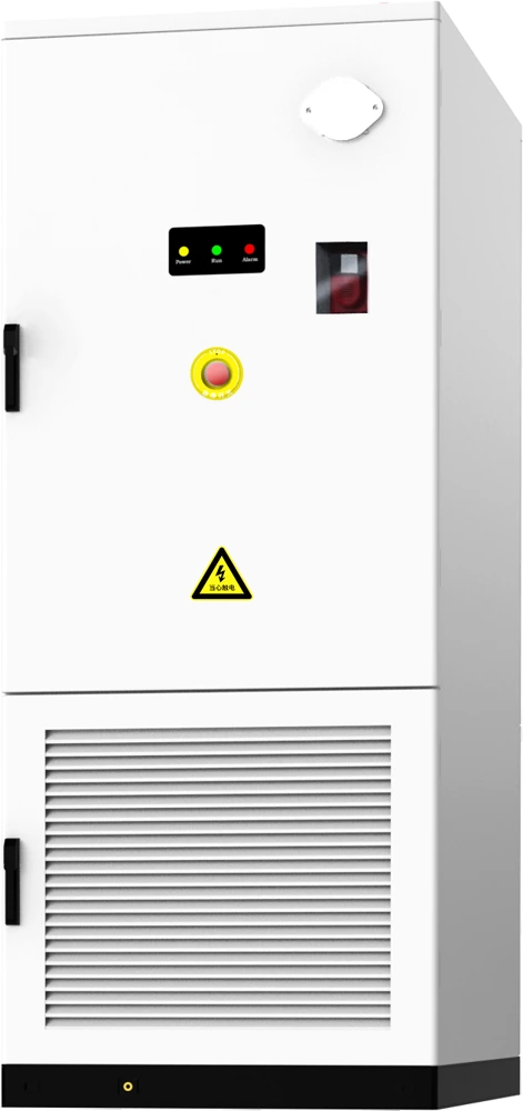
Start with the actual equipment configuration. An outdoor integrated cabinet, a DC battery cabinet with an external PCS and a container with separate power conversion equipment create different boundaries. The commercial cabinet range and containerized storage platform are useful starting points, but their dimensions alone do not complete a site layout.
Key takeaways
- Map water, access and maintenance constraints before accepting the battery location.
- Check enclosure ratings at the cabinet, pack and auxiliary-equipment level.
- Keep the approved layout, lifting plan and emergency response arrangements consistent.
On this page
- Walk the site before drawing the final footprint
- Treat flood exposure as a separate design question
- Check exactly what an IP rating belongs to
- Reserve space for cooling and heat rejection
- Follow the equipment from the entrance to its foundation
- Plan maintenance as a physical movement
- Coordinate emergency access with the approved safety design
- Use a site decision register
- Questions owners should resolve before purchase
- Turn the approved location into a buildable scope
Walk the site before drawing the final footprint
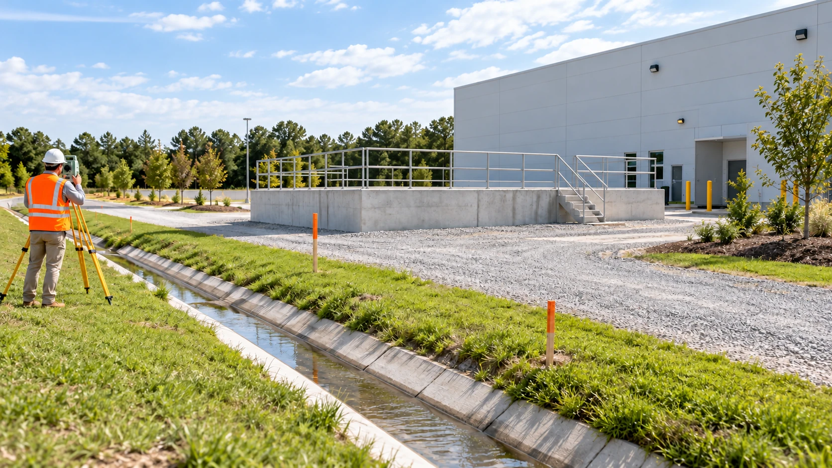
A site survey should produce an annotated location plan, photographs and a list of unresolved constraints. Include the owner, installer, electrical designer and maintenance representative. Each sees a different problem: the owner knows vehicle movements, the installer knows delivery access, and the maintenance team knows which doors and components must remain reachable.
Record existing services, underground utilities, surface levels, roof runoff, drains, loading bays and nearby equipment. Check whether a seemingly unused area becomes a vehicle turning zone or temporary storage space during busy periods. A location next to a wall may also receive reflected heat or collect debris. These conditions need review against the manufacturer’s requirements, not a guess based on a photograph.
The DOE BESS procurement checklist treats early project questions as part of development. The practical next step is to assign each unresolved site issue to a named person before requesting a fixed installation price. Otherwise, suppliers may quote different assumptions about groundwork, drainage or access.
Treat flood exposure as a separate design question
An enclosure rating does not establish that a battery installation can survive inundation. Water exposure includes several different conditions: rain on the enclosure, surface runoff around the base, water accumulating at cable entries, and floodwater surrounding equipment. Ask which conditions the product documentation actually addresses.
Review the site’s flood information and drainage with an appropriately qualified designer. The relevant question is whether batteries, PCS, auxiliary power, controls and access routes remain usable under the agreed design conditions. Raising the battery while leaving its external control panel or supply cable vulnerable can leave the project with the same operational weakness.
Also consider recovery. Can personnel approach the system after heavy rain? Can water collect beneath an access door? Will runoff from another structure cross the service area? A drawing should identify where water goes, not simply mark the battery on a concrete rectangle. Avoid choosing a plinth height before the site’s water conditions, structural requirements and cable arrangement have been evaluated.
The supplied 261kWh liquid-cooled DC cabinet is a concrete example: its table specifies IP54 for the cabinet and IP67 for the packs, with a 1000 × 1300 × 2200mm cabinet envelope. It also requires a separately selected compatible inverter or PCS. The site drawing therefore needs space and environmental review for that external equipment as well as the battery cabinet. Do not use the pack rating to approve the PCS location, and do not substitute the dimensions of the 125kW/261kWh integrated AC cabinet. These are different architectures with different installation boundaries.
Check exactly what an IP rating belongs to
Component and system ratings need separate entries in the equipment schedule. A protected liquid-cooled battery pack may sit inside a cabinet with a different rating. An indoor rack can have still another rating. None of these labels describes every cable gland, external inverter or junction box on the site.
For example, supplied product literature includes an IP54 cabinet and IP67 packs in a liquid-cooled DC configuration. That difference is useful for checking the equipment boundary. It does not justify describing the complete installation as waterproof, and it should not be transferred to another model merely because both products carry a similar energy label.
Request a diagram that identifies each outdoor enclosure and its rating, operating conditions and installation instructions. Check who supplies the cable-entry seals and whether site assembly changes the evaluated enclosure arrangement. Put responsibility for those details into the scope before equipment arrives. A purchasing description such as “outdoor BESS” is too broad to resolve them.
Reserve space for cooling and heat rejection
Cooling equipment needs a defined path for intake, exhaust and service access. Equipment placed close to another enclosure may recirculate warm air, obstruct a radiator or make filter changes difficult. The correct clearances depend on the exact cabinet and cooling arrangement.
The NREL, Sandia and SunSpec O&M guidance links battery temperature monitoring with performance and maintenance. For a new layout, translate that principle into an equipment-specific review: where is heat rejected, which surfaces must remain unobstructed, and what nearby equipment can change the local ambient condition?
Consider the whole row of equipment rather than one isolated cabinet. An exhaust path that looks clear in a single-unit drawing may face another unit after expansion. Future additions, sun exposure and nearby ventilation outlets belong on the location plan. Request the supplier’s continuous-power conditions and service requirements so that the site designer can assess the actual arrangement.
Follow the equipment from the entrance to its foundation
Delivery planning should show the entire route. Review the gate, road width, overhead obstacles, turning points, unloading location and final equipment position. A route that accepts a normal delivery truck may not accept the selected transport vehicle or lifting arrangement.
Ask for verified shipping dimensions, transport mass, centre-of-gravity information and the approved lifting or handling drawings. Do not infer shipping mass from installed energy capacity. Packaging, removable equipment and transport configuration can change what must be lifted. The lifting contractor and structural designer should work from the documents for the exact shipment.
The foundation review should cover equipment support, anchoring, cable entries and the surrounding working surface. Delivery and foundation assumptions must agree. If equipment can only be lowered from one side, that side needs to remain accessible when the delivery occurs. Check construction sequencing too: a fence installed early can block the final lifting route even when the finished layout appears workable.
Plan maintenance as a physical movement
Draw what must happen when a component is removed. Door swings, removable panels, access ladders, tools and replacement parts all need space. The service area should allow the approved maintenance method rather than only a person standing in front of the cabinet.
Ask the supplier to identify the largest replaceable component and describe its approved removal route. A pack may need a trolley or lifting aid; a cooling assembly may require access from a different side. Those requirements should appear in the service drawing and maintenance scope. They cannot be resolved reliably by adding a generic clearance around every object.
Separate routine access from major replacement access. A daily inspection walkway may be adequate for reading a display but unsuitable for replacing a heavy module. Keep both routes visible in the project record, and review how they interact with parking, production traffic and future building changes. This avoids accepting a layout that works only until the first major service event.
Coordinate emergency access with the approved safety design
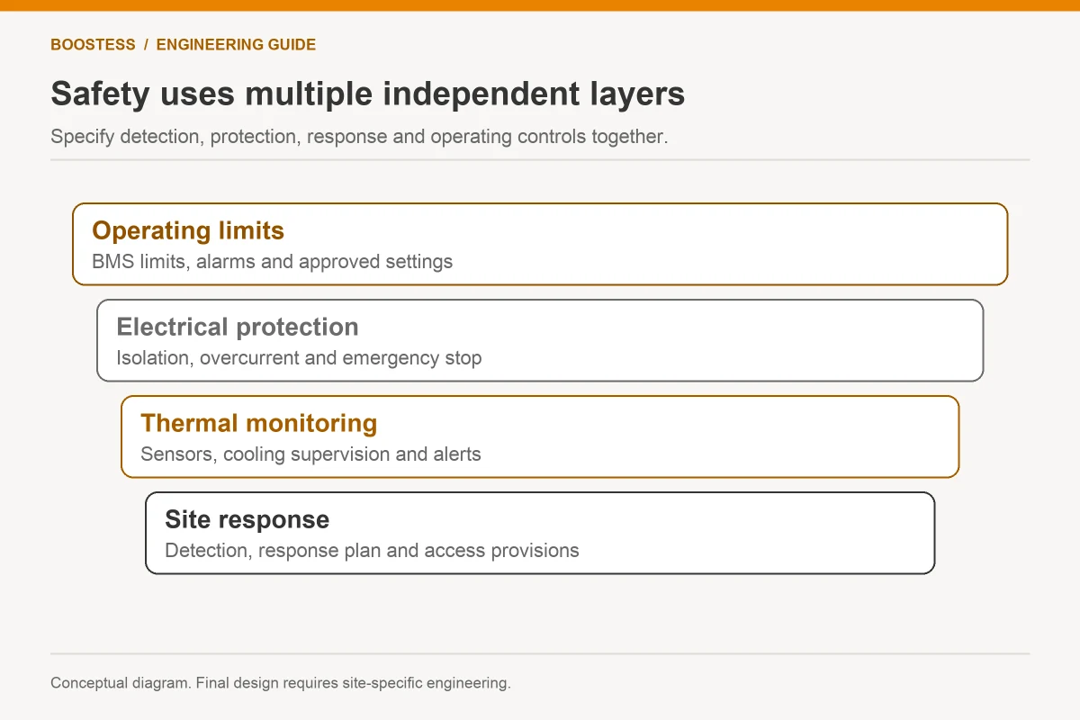
Emergency arrangements should identify access, isolation points, alarms and the information available to responders. The owner needs to know who controls the surrounding area and how the site’s operating procedures connect to the equipment instructions.
UL Solutions distinguishes system evaluation from thermal-runaway propagation testing. That distinction matters when reviewing a layout: the offered model’s evidence and approved installation conditions need to match the project. A standards logo or a component report does not establish a universal separation distance for every configuration.
Have the responsible professionals and authority review the specific arrangement. Keep emergency access routes clear in the site operating plan, including after later expansion. The final location should be coordinated with buildings, property boundaries and other equipment according to the applicable project requirements. A blog checklist cannot substitute for that approved design.
Use a site decision register
A short register makes competing locations easier to compare. The entries below are proposed planning questions, not universal acceptance limits.
| Review area | Evidence to request | Decision to record |
|---|---|---|
| Water exposure | Site levels, drainage assessment and equipment instructions | Accepted design conditions and remaining mitigation |
| Delivery | Verified shipment data and route review | Approved unloading and lifting arrangement |
| Cooling | Intake, exhaust and service drawings | Acceptable equipment orientation and surroundings |
| Maintenance | Component removal method and access plan | Routine and major replacement routes |
| Emergency response | Approved safety design and site procedures | Access, isolation and responsibility |
For each entry, name the document revision and responsible person. “Supplier to confirm” is a useful temporary note, but it is not closure. Ask what must be confirmed, by whom and before which milestone. The register can then support the layout approval, installation scope and handover record.
Questions owners should resolve before purchase
Can the battery go in the lowest unused part of the site?
Only after its water exposure, foundation, cable routing and access have been assessed. Space availability alone is not a siting decision. A low area may also collect runoff from adjacent roofs or roads.
Is the pack’s IP rating sufficient for an outdoor installation?
No single component rating answers that question. Review the complete equipment boundary, including cabinet, PCS, auxiliaries and site-installed connections, against the exact product instructions and site conditions.
Should maintenance clearance equal emergency separation?
They answer different questions. Maintenance clearance concerns approved work and removal access. Emergency separation follows the project’s safety design and applicable requirements. The layout must accommodate both.
Turn the approved location into a buildable scope
The final site package should include the approved location drawing, delivery and lifting arrangement, foundation details, cooling requirements, service routes and emergency access responsibilities. Check that all packages use the same equipment configuration and document revision. Record later changes before construction proceeds.
A supplier discussion becomes more useful when these conditions are available alongside load and operating-mode information. Review the system integration scope, then send BOOSTESS the equipment location, access constraints and site survey through a project assessment request so the proposed storage arrangement can be reviewed against a concrete site.